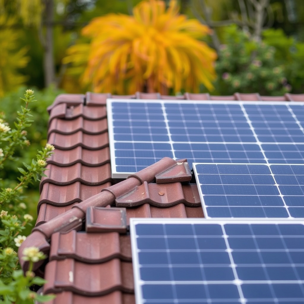
Integrating commercial solar PV systems into industrial and enterprise facilities requires a rigorous engineering approach. Unlike residential installations, commercial systems must manage high three-phase AC voltages, complex low-to-medium voltage switchgear integration, strict grid interconnection standards, dynamic power exportation limits, and ongoing operational maintenance. Design teams must balance initial capital expenditure with long-term performance ratios across standard 25-to-30-year operational lifespans. Achieving optimal performance requires selecting the correct architecture, understanding PV physics under local thermal stress, enforcing strict electrical protection codes, and establishing comprehensive operational protocols.
Commercial Solar PV System Architecture and Topology
Designing commercial solar PV systems ranging from 100 kW to multiple megawatts requires choosing between decentralized string inverters and centralized inverter architectures. Decentralized topologies utilize multiple high-capacity three-phase string inverters (typically rated between 50 kW and 350 kW). This configuration provides high granular Maximum Power Point Tracking (MPPT) resolution, simplifying string management and localized fault isolation. If a single string inverter experiences a component fault, the remainder of the array continues generating power, which minimizes system downtime. Conversely, centralized inverter topologies aggregate DC string power into multi-megawatt central units via large DC recombiner boxes. Centralized systems are typically suited for flat terrain ground-mounted arrays where balance of system switchgear can be centralized in an equipment enclosure, though they demand specialized maintenance personnel and introduce single-point-of-failure risks for large array blocks.
Optimizing the DC-to-AC sizing ratio—commonly referred to as the inverter loading ratio (ILR)—is essential to maximize annual energy yield. Standard commercial solar PV systems target an ILR between 1.25:1 and 1.4:1. Overloading the inverter allows the system to reach peak AC output earlier in the morning and sustain it later into the evening, compensating for real-world losses such as thermal derating, surface soiling, and module degradation. However, engineers must model local ambient temperature profiles against inverter thermal clipping limits. Excessive DC capacity in low-temperature, high-irradiance conditions leads to severe power clipping, delivering diminishing financial returns on incremental PV module capacity.
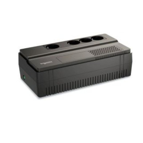
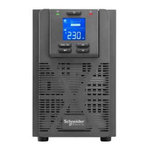
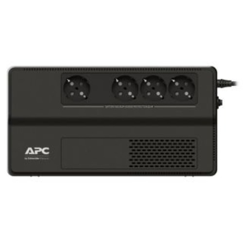
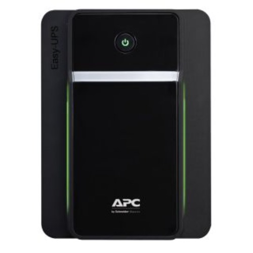
The balance of system (BOS) switchgear forms the electrical backbone of the installation. DC arrays connect through fuse-protected string inputs into DC combiner boxes equipped with integrated isolation switches. The AC outputs of string inverters are routed to AC re-combiner panels or directly to low-voltage switchboards. For high-capacity commercial installations connecting to medium-voltage utility networks, dedicated step-up transformers (such as 0.4 kV or 0.8 kV to 11 kV or 22 kV) are required. Integration with main facility switchboards must account for busbar ampacity ratings, fault current contributions from the solar system, and bidirectional utility metering. Facilities looking to integrate continuous power backup alongside solar arrays can reference EnergyX Egypt's specialized uninterruptible power supply solutions to ensure clean transfer during power transitions.
Module Technology Selection: TOPCon vs. HJT vs. PERC
Choosing the appropriate photovoltaic module technology directly impacts surface yield, power density, and temperature-induced performance losses. The industry transition from conventional Passivated Emitter and Rear Cell (PERC) technology toward advanced N-type cell architectures—specifically Tunnel Oxide Passivated Contact (TOPCon) and Heterojunction (HJT)—has redefined performance standards for commercial solar PV systems. A comprehensive analysis by the U.S. Department of Energy PV technology framework details how fundamental semiconductor physics govern these efficiency gains.
| Technology Parameter | PERC (P-Type) | TOPCon (N-Type) | HJT (N-Type) |
|---|---|---|---|
| Commercial Cell Efficiency Range | 20.5% – 22.0% | 22.5% – 24.0% | 23.0% – 24.5% |
| Temperature Coefficient (Pmax) | -0.34% to -0.38% / °C | -0.30% to -0.32% / °C | -0.24% to -0.26% / °C |
| Bifaciality Factor | 65% – 75% | 80% – 85% | 85% – 95% |
| First-Year Degradation | 1.5% – 2.0% | 1.0% | 1.0% |
| Annual Linear Degradation | 0.55% | 0.40% | 0.25% |
In high ambient temperature environments, temperature coefficients heavily influence daily generation profile. As PV cell operating temperatures rise above 25°C standard test conditions (STC), panel voltage drops. HJT and TOPCon modules exhibit lower negative power temperature coefficients compared to PERC, resulting in superior energy yield in hot climates. Furthermore, N-type substrates eliminate Light-Induced Degradation (LID) caused by boron-oxygen complexes inherent to P-type PERC wafers.
Bifacial module adoption yields additional generation when paired with reflective commercial roofing surfaces, such as light-colored Thermoplastic Polyolefin (TPO) or Polyvinyl Chloride (PVC) membranes. Depending on array tilt angle, surface albedo, and ground clearance, bifacial gains can increase rear-side generation by 5% to 20%. Ground-mounted commercial arrays utilizing single-axis trackers maximize this effect by keeping the module surface perpendicular to direct beam irradiance while capturing diffuse light on the rear face.
Structural engineering is critical when mounting arrays on commercial roofs. Engineers must perform structural load assessments to evaluate dead load (weight of modules, racking, ballast), live load (maintenance activities), wind uplift forces, and seismic requirements. Non-penetrating ballasted mounting systems are frequently specified for flat membrane roofs to maintain building envelope integrity. However, in geographic regions with severe wind exposure, mechanically anchored racking attached directly to structural steel purlins or concrete decks is mandatory.
Electrical Protection, Safety, and Code Compliance
Commercial solar PV systems operate at high continuous DC voltages—frequently up to 1000 VDC or 1500 VDC—requiring rigorous electrical safety and fault mitigation measures. Rapid shutdown protocols, such as those mandated by North American NEC Article 690.12 and adopted in international commercial guidelines, are intended to de-energize rooftop conductors to safe voltage levels (30 volts or less within 30 seconds) outside the array boundary during emergency response. Compliance is achieved using Module-Level Power Electronics (MLPE), such as microinverters or DC optimizers, or through string-level transmitter isolation devices that disconnect power directly at the module junction box.
Direct current arc faults represent a primary thermal risk in commercial arrays due to degraded module connectors, pinched insulation, or thermal expansion stress at electrical joints. Modern commercial string inverters incorporate integrated Arc-Fault Circuit Interruption (AFCI) compliant with UL 1699B standards. AFCI systems continuously sample DC line current spectral frequencies to identify signatures indicative of electric arcing, triggering an automatic inverter shutdown within milliseconds. Proper design must account for signal noise generated by adjacent electrical equipment to prevent nuisance tripping while retaining high sensitivity to genuine arc events.
Overcurrent Protection Devices (OCPD), such as gPV-rated fuses and molded-case circuit breakers (MCCBs), must be sized accurately. DC branch conductors require ampacity derating based on maximum circuit current, continuous loading safety factors (typically 125%), and elevated roof ambient temperatures. Surge Protection Devices (SPDs) must be deployed at critical junction nodes. Type 1 and Type 2 SPDs are required on both the DC inputs of inverters and main AC distribution switchboards to protect sensitive internal components from atmospheric lightning transients and utility switching surges.
Grid Interconnection, Power Quality, and Export Limitation
Grid integration requires compliance with stringent utility standards. Interconnection requirements for commercial solar PV systems are governed internationally by standards like IEEE 1547-2018 standard for distributed energy resources. Modern commercial inverters must provide active grid-support capabilities, including autonomous volt-VAR regulation, volt-watt control, frequency-watt response, and low/high voltage and frequency ride-through capabilities to prevent localized grid instability.
- Volt-VAR Control: Inverters inject or absorb reactive power based on measured grid voltage to suppress voltage spikes on local utility feeders.
- Frequency-Watt Response: Inverters automatically curtail active power output if grid frequency exceeds designated operational thresholds.
- Anti-Islanding Protection: Mandatory active and passive loss-of-mains detection mechanisms de-energize the PV system within cycles if grid supply is interrupted, protecting utility line workers from backfeeding.
Many commercial facilities operate under net-metering constraints or zero-export mandates enforced by utility operators. To comply, dynamic export limitation systems are implemented at the main service entrance. A digital power meter measures real-time power flow at the utility interconnection point and communicates continuously with inverter power controllers over high-speed Modbus TCP or Ethernet networks. If load demand drops below PV generation, the controller adjusts inverter output within seconds to prevent unauthorized reverse power flow into the grid.
Power quality management requires controlling Total Harmonic Distortion (THD), eliminating phase imbalance, and preventing voltage flicker. High-frequency switching circuits in modern inverter topologies produce minimal current THD (typically under 3% at rated power). However, improper cable sizing or unequal string distribution across phases can introduce phase imbalance, requiring careful system balancing during the detailed design phase. Facility engineers evaluating broader site integration can review EnergyX Egypt's commercial solar energy services to analyze utility point-of-common-coupling requirements.
Commissioning, Testing, and O&M Protocols (IEC 62446-1)
Comprehensive commissioning ensures that commercial solar PV systems perform safely and deliver predicted output. Formal verification must adhere to international standard IEC 62446-1 testing and documentation standards. Commissioning procedures fall into Category 1 (standard inspection and testing) and Category 2 (advanced diagnostic testing) protocols.
- Continuity of Protective Earthing: Verification that all metallic racking, array frames, enclosures, and conduit systems are bonded to earth ground with low resistance.
- Polarity and Open-Circuit Voltage (Voc) Testing: Measurement of each string under steady irradiance to verify correct polarity and match voltage against string design calculations.
- Short-Circuit Current (Isc) and String Testing: Testing string short-circuit currents to identify high-resistance connections or faulty module diodes.
- Insulation Resistance Testing: Applying continuous DC test voltage (500V or 1000V) between active array conductors and earth ground to measure insulation integrity prior to energization.
Advanced diagnostic procedures include I-V curve tracing, infrared (IR) thermography, and performance modeling. I-V curve tracing compares real-world voltage-current characteristics against theoretical curves, diagnosing issues such as cell mismatch, localized shading, PID (Potential Induced Degradation), or excessive cable resistance. Aerial or handheld infrared thermography conducted under high irradiance (>700 W/m²) identifies hot spots caused by cell micro-cracks, failed bypass diodes, or loose electrical connections.
Continuous monitoring relies on industrial SCADA or enterprise cloud telemetry integrated with site weather stations. Key Performance Indicators (KPIs) include the Performance Ratio (PR), calculated as the ratio of actual AC energy yield to theoretical energy yield based on plane-of-array (POA) irradiance and temperature measurements. Operational and maintenance protocols must mandate routine inverter heat-sink and fan cleaning, torque verification on electrical terminations, structural bolt audits, and scheduled module soiling management. For turn-key implementation, system modeling, or engineering advice, facility owners can request an engineering quotation directly from EnergyX Egypt's technical engineering team.