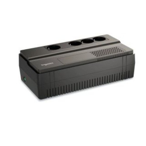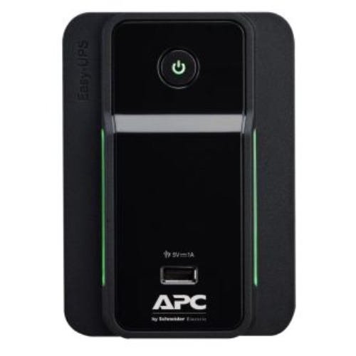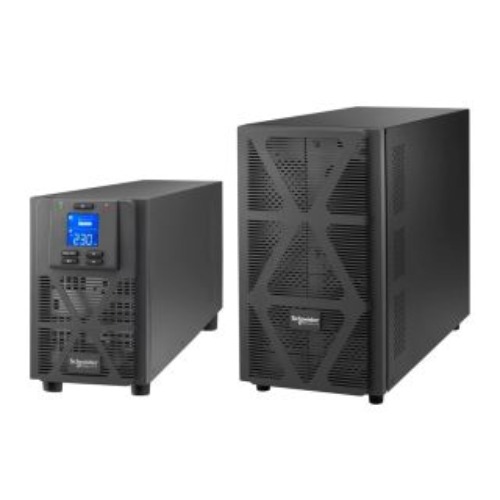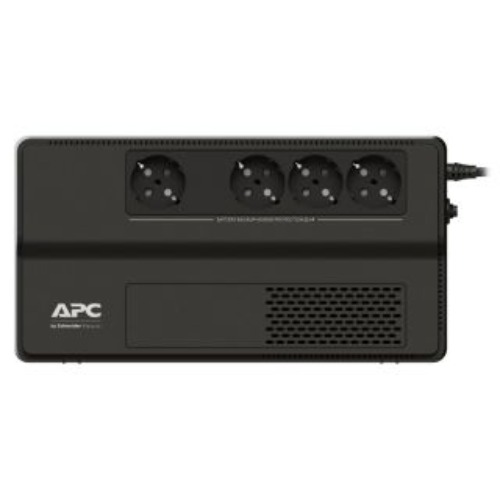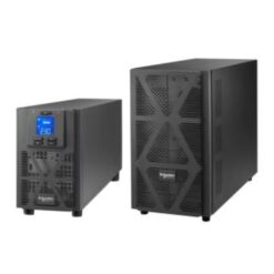
Uninterruptible Power Supply (UPS) systems serve as the cornerstone of power quality and continuity for data centers, medical facilities, industrial automation lines, and critical telecom infrastructure. Designing a resilient backup power system requires a deep understanding of standard topology mechanics, load power factors, harmonic mitigation, dynamic energy storage choices, and system-level redundancy models.
UPS Topologies and Operational Mechanics per IEC 62040-3
The operational behavior and power protection capabilities of a UPS are defined by international standards. According to the IEC 62040-3 performance specification standard, UPS systems are categorized into three distinct operational topologies based on output voltage and frequency independence from the incoming utility supply:
- Voltage and Frequency Independent (VFI - Online Double Conversion): Modern VFI systems continuously convert incoming AC power to DC via a rectifier, charging the battery bank while simultaneously synthesizing a regulated AC output via an inverter. Because the load is decoupled from incoming mains disturbances, line phase shifts, frequency fluctuations, and utility blackouts result in continuous power delivery with zero transfer time.
- Voltage Independent (VI - Line-Interactive): In VI configurations, the inverter remains connected in parallel with the critical load. An Automatic Voltage Regulator (AVR) tap-changing transformer compensates for under-voltage and over-voltage conditions without depleting battery reserves. Upon main supply failure, an automatic transfer switch disconnects utility power within 2 to 10 milliseconds.
- Voltage and Frequency Dependent (VFD - Standby / Offline): VFD systems route utility power directly to the load during normal operations. The inverter engages only when utility voltage strays outside tolerable bands. While highly efficient, the inherent 5 to 12 millisecond transfer delay makes VFD systems unsuited for sensitive non-linear data processing hardware.
For mission-critical applications where transient spikes or momentary power losses lead to data corruption or hardware damage, VFI online double conversion is the industry baseline. For a comprehensive overview of topology efficiency trade-offs, consult Schneider Electric's white paper on UPS topologies.
| Topology Classification | Transfer Time | Voltage Regulation | Frequency Regulation | Typical Target Application |
|---|---|---|---|---|
| VFI (Online Double Conversion) | 0 ms (Zero Delay) | Continuous Active Regulation | Independent Synthesized AC | Data Centers, Healthcare, Precision Process Control |
| VI (Line-Interactive) | 2 - 10 ms | Step Regulation via AVR Transformer | Grid Dependent | Edge Telecom Equipment, Distributed IT Racks |
| VFD (Standby / Offline) | 5 - 12 ms | None (Direct Utility Feed) | Grid Dependent | Non-critical Workstations, POS Terminals |
Power Capacity Sizing: kW, kVA, and Load Dynamics
Accurate electrical capacity planning requires a clear distinction between active power measured in kilowatts (kW) and apparent power measured in kilovolt-amperes (kVA). The operational power factor (PF = kW / kVA) dictates the usable work delivered by the UPS unit.
Legacy double-conversion UPS units often carried an output power factor of 0.8 or 0.9, meaning a 100 kVA UPS could only support 80 kW or 90 kW of real load. Modern UPS systems feature a unity power factor (PF = 1.0), delivering matching kW and kVA ratings (e.g., 100 kVA / 100 kW). When sizing a system, engineers must account for current crest factor tolerances, non-linear load harmonics, and inrush currents from downstream step-down transformers or direct-on-line motors.
- Steady-State Sizing Formula: Total Active Capacity Required (kW) = Total Connected Active Load (kW) × Diversity Factor ÷ Desired Maximum System Utilization Target (typically 75% to 80%).
- Crest Factor Tolerance: Computing loads with switch-mode power supplies draw peak current at peak voltage. Ensure the UPS inverter can supply peak current ratios of 3:1 without tripping over-current protection.
- Inrush Considerations: Inductive equipment and high-efficiency isolation transformers draw peak magnetizing currents upon energization. Sizing margins must absorb these temporary transients without transferring the unit to bypass.
Engineers must verify individual server, motor driver, and inductive load power factor and crest factor parameters directly with equipment vendors prior to final UPS kVA/kW sizing calculations. To evaluate your site load profiles, explore EnergyX turnkey UPS systems and power assessment services.
Redundancy Configurations and Bypass Architectures
To prevent single points of failure in power delivery, enterprise UPS architectures incorporate module redundancy and dedicated bypass pathways.
N+1, 2N, and 2N+1 Redundant Configurations
An N configuration provides exact power capacity matching the operational load without safety margin in hardware failure. An N+1 system adds one extra power module or unit into a parallel bus; if one module experiences an internal component fault, remaining units absorb the load without interruption. High-tier critical facilities deploy dual-bus 2N or 2N+1 architecture, providing two completely independent, concurrently maintainable power paths from separate utility feeds down to dual-corded load power supplies.
Static Automatic Bypass vs. Manual Maintenance Bypass
Every online UPS includes a solid-state Static Bypass Switch that acts as an ultra-fast static transfer path. If an inverter over-temperature condition or short-circuit overload occurs, the static switch transfers the load to raw utility power in under 1 millisecond. For routine maintenance, servicing, or total module replacement, a break-before-make or make-before-break Manual Maintenance Bypass Cabinet (MBC) completely isolates the internal UPS electronics while safely powering the load directly from utility lines.
Input Harmonic Mitigation
Historically, input rectifiers injected significant harmonic current back into the facility distribution grid, forcing generator oversizing. Modern transformerless UPS designs utilize Active Front End (AFE) rectifiers built with Insulated Gate Bipolar Transistors (IGBTs). These systems maintain an input Total Harmonic Distortion (THDi) below 3% and an input power factor near unity (>0.99), ensuring seamless generator synchronization and grid compatibility.
Energy Storage Selection: VRLA, Lithium-Ion, and Flywheels
The energy storage system supplies DC power to the UPS inverter during AC utility power outages. Selecting the correct battery chemistry or mechanical system depends on runtime requirements, thermal constraints, floor weight capacity, and total cost of ownership (TCO).
| Parameter | Valve-Regulated Lead-Acid (VRLA) | Lithium Iron Phosphate (LiFePO4) | Kinetic Flywheel Storage |
|---|---|---|---|
| Footprint & Weight | Heavy / Large Footprint | 60% Lighter / 50% Smaller Footprint | Extremely Compact Footprint |
| Operating Temperature | 20°C - 25°C Strict Optimum | 20°C - 35°C Flexible Tolerance | 0°C - 40°C Broad Envelope |
| Expected Service Life | 3 - 5 Years (Standard) / 10 Years (Long Life) | 15 Years Continuous Operation | 20+ Years Mechanical Life |
| Cycle Durability | 200 - 500 Deep Discharge Cycles | 2,000 - 4,000 Deep Cycles | Unlimited Rapid Charge/Discharge |
| Bridge Runtime | Scalable (5 mins to Hours) | Scalable (5 mins to Hours) | Short Duration (15 to 45 Seconds) |
While VRLA batteries maintain low initial capital expense, Lithium Iron Phosphate (LiFePO4) solutions offer lower TCO over 15 years due to minimal cooling demands, built-in Battery Management Systems (BMS), and reduced replacement cycles. Kinetic flywheels provide mechanical backup that bridges the brief gap required for emergency backup generators to start, synchronizing cleanly without chemical degradation.
Proper battery system integration requires reviewing safety standards such as the IEEE Std 1184 guidelines for stationary battery systems. Crucially, DC bus short-circuit capacity and protective device clearing times must be verified with battery rack manufacturers to ensure safe breaker trip coordination.
Regulatory Compliance and Emergency Power Transfer Standards
Critical power designs must align with regional safety codes and industry standards governing transfer speed and runtime endurance:
- NFPA 110 and NEC Article 700: Life safety emergency power supply systems (EPSS) require emergency generators and transfer switches to restore life safety loads within 10 seconds of utility failure. UPS units provide continuous clean voltage bridging this critical 10-second starting window.
- Healthcare Facilities (IEC 60364-7-710): Isolated power supplies and Group 2 medical locations mandate localized backup power sources capable of engaging in under 0.5 seconds for critical operating room environments.
Confirm regional regulatory compliance requirements for emergency power source transfer speeds, runtime duration, and secondary power source isolation prior to installation commissioning. For expert site evaluation and power system planning, consider contacting the EnergyX engineering team for custom consultations.